1. Parts and assembly
Build the electronics first. The enclosure and cameras can come later.
Shopping list
These are the parts used in the reference model. Product links identify the part; prices and availability vary. P02 is the modeled reference; the enclosure is specific to that adapter. Check your board label before buying matching enclosure parts.
| Part | Qty | What to look for / links |
|---|---|---|
| Raspberry Pi 5 | 1 | The reference BOM uses the 2 GB model. Official product and resellers. More RAM is useful for compiling locally. |
| Raspberry Pi Active Cooler | 1 | SC1148, fits the Pi 5 fan header and mounting holes. Product · installation brief. |
| Official 27 W USB-C power supply | 1 | Use the version for your mains socket and its attached cable. Product and resellers. |
| microSD card | 1 | Reference: 64 GB A2. The NIC occupies the Pi’s PCIe connection, so this build boots from microSD. Raspberry Pi cards. |
| PCIe adapter/baseboard | 1 | 52Pi / GeeekPi P02, EP-0219. Open-ended x1 slot, custom FFC, pillars and screws. 52Pi store · Pi Hut · assembly instructions. |
| Intel dual-port NIC | 1 | I350-T2 V2 / I350T2V2BLK, with the low-profile bracket for this enclosure. Intel specifications · supplier comparison. |
| Ethernet patch cables | 1 per arm | Cat6 in a suitable length; reference BOM: Goobay 93571, 3 m. One extra cable if the Pi’s built-in Ethernet is your uplink. |
| Mechanical support | 1 | Support the card’s bracket on a mounting plate or use the printable enclosure. |
The Intel card is physically x4; the P02’s open-ended slot accepts a longer card while providing one PCIe lane. This is why a closed x1 slot is not an interchangeable substitute. Follow the P02 manufacturer’s assembly drawing for the connector and power arrangement. Other adapters, including uPCIty Lite, use a different layout and power arrangement; the P02 case is not a universal Pi case.
Put the stack together
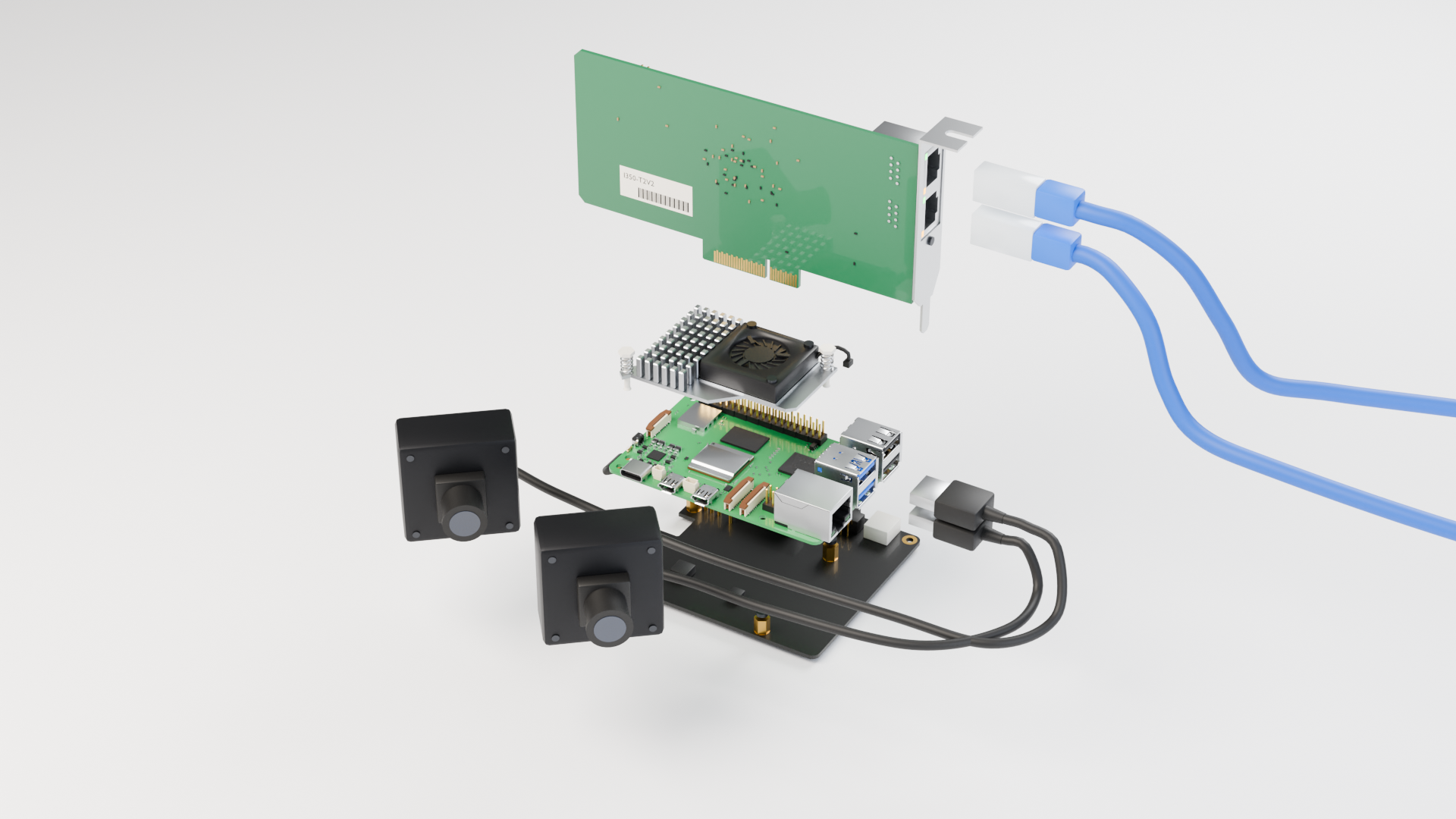
- Disconnect power. Fit the Active Cooler’s thermal pads and push pins as its instructions show, then plug its lead into the Pi’s four-pin fan connector.
- Mount the Pi on the P02 pillars. Use the supplied hardware and check the P02’s power contacts align. Keep the cooler’s inlet clear.
- Connect the supplied PCIe ribbon. Use the Pi’s PCIe connector and the P02 connector; follow the manufacturer’s contact orientation and close both latches. Do not force it into a camera/display connector.
- Seat and support the Intel NIC. Seat its edge connector in the open-ended slot, supporting the bracket so plugging in Ethernet cannot lever the card out.
- Insert the microSD card and attach cables. Supply Pi power through the official USB-C PSU after assembly. Follow the adapter instructions if using an external slot supply.
Which port goes where?
| Connection | Destination |
|---|---|
| Intel port labeled L in the enclosure | Left robot control unit |
| Intel port labeled R in the enclosure | Right robot control unit; leave empty for one arm |
| Pi’s built-in Ethernet or Wi-Fi | Your laptop / lab network, carrying Zenoh and SSH |
| Pi USB ports | Optional cameras |
| Pi USB-C power connector | 27 W supply |
Labels are a wiring convention, not Linux interface names. Identify and label the two interfaces in step 2; do not assume port order from the name alone.
Optional cameras and input devices
The reference BOM lists two ELP-USBGS1200P01 / AR0234 USB cameras. The CAD models use
generic camera housings; the sensor and lens are not verified by these models. Check a
camera’s V4L2 formats before choosing it for franka-cam.
Manufacturer example.
Cameras are not required for control, and a Quest headset is optional:
franka-vr-teleop drives a node-served arm from one. An
integration for any other input device is yours. See
peripherals and recording.