4. Optional enclosure
The controller works without a printed case. This two-part enclosure supports the Pi 5 + Active Cooler + P02 + low-profile I350-T2 V2 reference assembly.
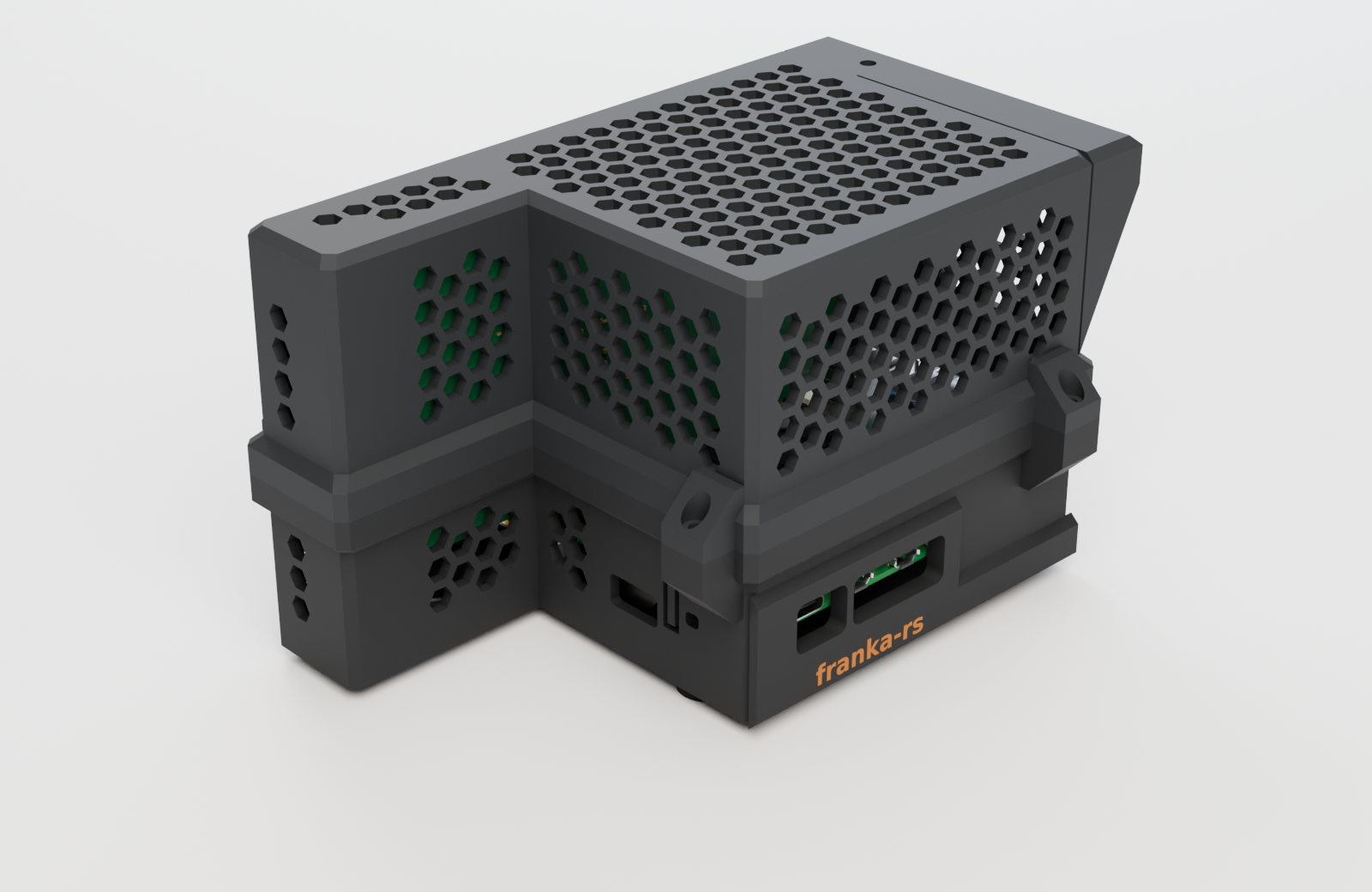
The current downloads include a dedicated slot and reinforced supports for the Intel bracket’s folded edge. Use the base and lid from the same print bundle.
Look inside
Open the interactive 3D viewer to rotate the case, switch to the electronics, or inspect the exploded assembly. No plugin is required.
The Pi geometry comes from official CAD. The cooler, P02 and NIC are modeled from manufacturer drawings and photographs; some dimensions are estimates. Check your actual adapter, card and bracket before printing. Other boards or brackets may not fit.
Download the right file
| You want to… | Download |
|---|---|
| Print both parts | Print bundle: ZIP — two STLs and a 3MF |
| Open both parts in a slicer | enclosure.3mf |
| Slice one part | base.stl · lid.stl |
| Edit the enclosure in CAD | base.step · lid.step |
| View the enclosure with electronics | enclosure-scene.glb |
| View the electronics alone | assembly.glb · assembly-exploded.glb |
STL / 3MF are for slicing; STEP is for editing; GLB is for viewing. The GLB includes electronics and cables and must not be treated as a printable case. The 3MF contains both meshes and their layout, not a tested printer profile.
Model sources and attribution · File sizes, revision timestamps and SHA-256 hashes.
Slice a fresh print
Use the STLs in their supplied print orientation, or open the 3MF and select your own printer and material. The design notes specify this starting point:
| Setting | Design starting point |
|---|---|
| Nozzle / layer height | 0.6 mm / 0.3 mm |
| Walls / top and bottom | 4 perimeters / 5 layers |
| Infill | 25% gyroid |
| Supports | Designed for no supports; inspect bridges in your slicer |
| Bed | Both parts arranged on a 220 × 220 mm plate |
| Base / lid orientation | Base floor on bed / lid roof on bed |
Review the sliced result before printing; extrusion width, bridging, material and machine settings affect the fit. The earlier 0.4 mm G-code is stale and is intentionally not provided. Generate new G-code from this geometry for your printer’s 0.6 mm profile. Let the bed cool before removing the parts; flex the plate rather than prying at the port wall.
Fasteners and assembly
In addition to the P02’s pillars, the design calls for:
- 7 M2.5 × 4 mm heat-set inserts (holes sized at 3.6 mm diameter).
- 5 M2.5 × 8 mm socket-head screws: four lid screws and one bracket clamp screw.
- 4 M2.5 × 10 mm floor screws and 2 M2.5 × 6 mm P02 mounting screws.
- 4 adhesive rubber feet, 12.7 mm diameter × 3.5 mm.
Fit the inserts, connect the ribbon, and mount the P02/Pi stack in the base. Check screw engagement against the actual pillar threads. Seat the card through the bracket groove and lower guide, with the bracket’s folded edge in its dedicated slot; fit the lid so the card enters the upper guide, then secure the lid and bracket. Avoid forcing the card or overtightening the clamp.
The design has undergone CAD clearance and insertion checks, but bracket position and port heights still include estimates. Thermal performance and the revised printed fit have not been established by these model checks. Keep the Active Cooler and ventilation unobstructed.